SURVEY OF VICTORIA.
BY
R. L. J. ELLERY, Esq., C.M.G., I.R.S., F.R.A.S.
Read before the Victorian
Institute of Surveyors,
September 4th, 1891.
Melbourne :
J. C. STEPHENS, PRINTER, 146 ELIZABETH STREET.
BRIEF SKETCH OF THE GEODETIC SURVEY OF
VICTORIA.
BY R. L. J. ELLERY, Esq., C.M.G., I.R.S., F.R.A.S.
Read before the Victorian
Institute of Surveyors,
September 4th, 1891.
THE Geodetic Survey of Victoria was commenced in September, 1858, and its operations were practically terminated in 1872.
The circumstances that led up to this form of general or systematic survey may be briefly summarised as follows :-
The demand for land in 1857 was generally in excess of the power of the Survey Department to meet it, and agitation was on foot for selection before survey. To meet the difficulty the Surveyor-General of the time, Mr. C.W. Ligar, advised the Minister, the Honourable Mr. Gavan Duffy, to institute a system of meridian survey, somewhat analogous to that adopted in many parts of the United States, by which large areas could be rapidly included within meridians and parallels of latitude, or their chordal lines, the areas so marked out to be let out for sub-divisional survey by contract. The Minister adopted the suggestion, and Parliament was asked for the requisite votes. The original scheme was somewhat ambitious, as it contemplated a complete survey of the Colony within a small number of years, end required a heavy yearly subsidy for its prosecution. The scheme did not secure the entire confidence of Parliament, and lengthy debates took place. Eventually the Minister's proposition was in part agreed to, and a very much smaller sum than estimated was granted.
In July,1858, I was invited by the Surveyor-General to take charge of the Geodetic or Meridian Survey. This invitation I accepted, and shortly had associated with me an assistant, Mr. Richard Petty, and several survey parties in charge of non-commissioned officers of the Royal Engineers, who had recently been drafted from England at the instance of Captain Clarke, former Surveyor-General. My instructions were to enclose large areas by true meridians and parallels in the plains between the coast ranges and the Murray, and also in the Western districts, especially in the country traversed by the Glenelg and Brannon. To then subdivide these larger areas into blocks of one-tenth of a geographical degree, which would be a suitable area for sub-divisional survey by contract. In the middle of September, 1858, the survey was actually started, the first operation being the determination by triangulation of the difference of longitude between the Williamstown Observatory and a point selected in the Royal Park, as the starting point of the first chief meridian which was to be run from the waters of the Bay (near the Port Melbourne Railway Station) to the River Murray. For this purpose, a base of two miles was measured on the rails of the Williamstown and Melbourne Railway with a standard chain. This meridian was traced, cleared, and measured as far as the intersection of the 37th parallel of latitude, and these, with the requisite preliminary operations, occupied till March, 1859, when the measurement of the first standard parallel (latitude 37' 48') was commenced, starting from the first chief meridian near Flemington. This was measured as far as the intersection of the second standard meridian, approximately 144 E. long., near Shelford. A most careful chain of triangulation was carried along this parallel to fix the intersections of the secondary meridians. The first chief meridian was meanwhile carried on to the Murray. The second chief meridian was cleared and traced to the northwards. By February, 186o, besides the work already referred to, the 37th parallel had been laid out through a portion of Anglesey, and Geodetic blocks marked out on that parallel as well as on the first chief meridian. The 5th and 6th secondary meridians were also run from the first parallel northwards towards the boundary of the colony.
It will therefore be seen that up till February, 186o, the operations had been confined to astronomical determinations of positions and directions, line tracing and measuring, and some little triangulation. I will now briefly describe the methods followed in these operations.
MERIDIAN LINES.
These were lines run, cleared, marked, and measured, conforming in direction, as closely as was possible with large portable instruments, to the true astronomical meridian. The initial point being selected, the instrument, either a transit instrument, or the 18-inch theodolite, was mounted over it, and a careful series of azimuth observations with selected stars obtained from which the true direction of the meridian was deduced. With these azimuths, points were put down north and south of the instruments at distances seldom less than five miles, and frequently twenty miles or more. Solid posts, firmly fixed and surrounded at the base by cairns, or the trunk of a tree squared with the axe, were the marks generally used for these primary points. On these were fixed referring marks. To do this work a system of signalling had to be adopted, which for the shorter distances was done by flags, and for longer by help of the heliotrope, then a new instrument in Australia. Great difficulty was often found in accurately and finally fixing a distant mark, especially in cloudy weather; on fine days with the heliotrope it was rapidly managed, the heliotrope itself forming the point and signal instrument as well. There was often great difficulty experienced by advance or clearing parties in timbered country in getting into line, by reason of the invisibility of the observing station. The plan of making a smoke had then often to be reverted to. The advance party having got as near the line as could be estimated or by prismatic bearings, lit a fire and raised a smoke, which could be picked up by the observing party. In some cases a return signal could be obtained by an intermediate signal man, but in most cases the azimuth only of the smoke could be measured by the observing party which sent on a messenger to give the distance the advance party had to move to get near enough to the line to clear it, preparatory to fixing the true point. As will be imagined, numerous devices had to be resorted to in some places to overcome difficulties presented by features of the country.
Between the primary points thus fixed secondary points were fixed, varying from one to two (or in some cases more) miles apart, according to circumstances, with a portable transit instrument, and between these the line was traced, and in part cleared. The lines were not cleared fully through all the valleys and low ground when they ran through alienated or unrequired Land, and the lines were only traced and cleared completely when the land being traversed was to be blocked out for survey. In the latter case, in addition to primary and secondary points, intersection points were established to mark the corners of degree, or one-tenth degree blocks. These intersection points consisted of squared posts well sunk in the ground, and having a cast iron cap, with broad arrow and number (indicating block corner) on it. Diverging from this as centre four deep trenches were dug in the direction of the boundary lines, about six feet long. In some cases when meridians .were run from an initial point in order to reach a distant district required for survey, very distant primary points on ridges and high grounds were rapidly fixed and all intermediate marking was left, in order to get the meridian transferred as rapidly as possible on to the required areas.
Obtaining the intersection of parallels on the meridian and tracing them east or west, presented more serious difficulties, and the question arose whether to trace the true curve direct, a chord of the parallel for a whole degree, or a chord of a parallel for one-tenth degree. And then again, would it be best to trace a perpendicular to the meridian and measure back for the intersection of the one-tenth degree meridians, or run the chordal lines at once? In fact all methods were tried, but that of running a perpendicular to the meridian, and measuring south to the true intersection of the parallel at each one-tenth meridian was preferred, although some of our surveyors, especially those with large first-class theodolites, adhered to the method of setting off the chord of one-tenth of a degree at once and tracing on to the next intersection. In a few instances when a parallel ran over land not wanted for survey a chordal line of one full degree was run, marking only the high points and ridges as in the case of meridians. In every case. the actual measurement of the parallel or chordal line was the laborious part. Until the primary triangulation was commenced this was always done by a special chain of small triangles springing from a base of a mile or two very accurately measured. Such triangulation was always done by specially good theodolites, generally 8" to 10". Before triangulation the line was always measured by double chaining, one party following another; this greatly expedited the after triangle measures by showing approximate intersections. To obtain the initial point of a parallel on a primary meridian, before the trigonometrical survey had advanced, a tedious series of astronomical observations were necessary for determination of latitude. The methods used were prime vertical transits, ordinary star altitude, and zenith distance differences. The astronomical latitude of a point on a meridian being thus determined a short measurement along the meridian to the computed point of intersection was the only remaining operation to complete the work, for the latitude was always approximately known before setting up the Observatory on the line.
The Officers employed up to the end of September, 1859, were as follows :—
|
Superintendent |
R.L.J. Ellery, from 1st August, 1858 |
|
Assistant |
R. Petty, fromv20th August, 1858 |
|
Assistant |
A.C. Allan, from April 1859 |
|
Assistant |
E. de Verdon, from April 1859 |
|
Assistant |
P. Chauncey, from April 1859 |
|
Assistant |
T.W. Pinniger, from 20th July, 1859 |
|
Computer |
P. Crenion, from April 1859 |
The total expenditure up to this date
for salaries
The total expenditure up to this date for salaries, wages, equipment, instruments, building stations, etc., was £5,451.
It had been early found by experience that the process of connecting distant localities with the chief meridian by running and measuring meridians through great lengths of country not required for survey was not sufficiently expeditious with the strength at command, and it was soon found desirable to push forward a primary triangulation so as to more rapidly reach the distant districts and connect the work generally. Already trigonometrical points had been erected on prominent hills northwards from Melbourne to the Murray, and a considerable number in the Western District also, which had involved a great amount of labour and cost in clearing mountain tops and so on. This work had been set on foot by Captain Clarke, R.E., two or three years previously, the party of sappers and miners from England already mentioned having been placed in charge of the clearing parties for this purpose.
In January, 1860, a site for a base line was selected on the Werribee Plains, 4.942 miles long. The one end (South end) being within the Railway enclosure, about two miles E. of the Werribee station, the N. end bearing 304° 36' 31", 26o91.826 feet, or 4.9416 miles, and in a direct line with a hill named Green Hill, on the west side of the Werribee River, 5.651 miles distant from the N. end. On this hill a permanent point was established, and the measured base was ultimately extended by triangulation to this point, which was named the Green Hill extension.
The ends of the measured base were marked by solid masses of masonry built five feet into the ground, capped by a heavy stone with large plugs of gun metal, having platinum centres on which was marked a fine terminal dot. Over this cap-stone was placed a heavy cover-stone for protection, and above all a timber pyramid with pinnacle carefully centred over the platinum point to help in alignment and subsequent triangulation for checking, and for extension and expansion of the base. The Green Hill extension terminus was marked by a heavy sunk stone with centre similar to the ones already described. The actual measure of the base was commenced on 29th January, 186o, and ended 29th May and minor triangulations for extension to Green Hill was completed June 12th.
First a complete measurement of the 4.942 mile base was made by level bars, and then a re-measurement of 2.11 miles of the S. end was made with bars following the general inclination of the ground. The apparatus used was as follows :-
Three measuring bars, ten feet long, of iron 1 inch square, with the ends turned round for about 4 inches in length, one end being finished quite flat and polished, while the other end was a polished segment of a sphere of 5 feet radius. Each bar was provided with levels, thermometers, and aligning vanes, and were encased in wooden boxes for nearly the whole length, about two inches at each end only projecting. For supporting the bars, well-made strong pine tripods, or trestles, of various lengths were used, varying from 12in. to 42in. in height, the top being a triangular frame 12in. on the side, the three feet being at the points of a triangle of 20 inches. On these trestles were placed instruments called camels, which consist of a heavy brass tripod with levelling screws, through the centre of which, in a well-finished socket, rises a stout prism of brass actuated by a strong screw underneath for raising and lowering the prism. On the top of the prism is a little table, or slide-rest, with rollers, and screw slow motion work all of metal. To receive the three tripod levelling screws, metal sockets are fixed on the top frames of the pine tripods, or trestles. In order to place a bar two trestles are put up 5 or 6 ft. apart, with a Camel on each, and the bar laid on the Camel tables, on which they fit easily, and, resting on the rollers, can be moved endways with facility and great smoothness. One Camel carries a slow motion or tangent screw for moving the bar lengthways, while both have screws for sideway motion. And the vertical motion for raising, lowering, and levelling the bars is given by the prism and its screw.
The line having been laid out and carefully levelled, and the stages arranged, for although the line was apparently level there was a difference of 14.5 feet in the five miles, the operation of trestling was first undertaken for a stage as follows :-
The line being laid out, pegs were driven at intervals exactly in the centre of where each trestle would come; around this strong pegs were driven, projecting above ground sufficiently to carry the trestles at the required height for that part of the stage, the length above ground being determined previously by the original levelling, so that a pegged stage would perhaps commence with pegs flush with the ground, and end with some two feet long, or vice versa. On these pegs, which were level one with another, were laid triangles (triangular frames of pine wood), on which again the trestles were placed.
To prevent exposure of the bars to sun or rain during measurement a kind of tent was used, consisting of a pair of strong but light frames, 12 feet long and 9 feet high, hinged together at the top and covered with canvas laced to the frames, and in vertical cross sections were like the letter A. There were four tents, and four men could move one quickly. As soon as the back bar was done with, it was moved forward to the empty tent in front, and the tent-bearers then carried the back tent to the front, and so on. The party consisted of Officer in charge and Observer, Observer of alignment, Recorder, two Bar men, two Camel men, and four tent-bearers : eleven in all. The trestle and staging party had generally eight men, and were always considerably in advance of the measuring party.
To describe the method of measurement it will be
best to take the case of starting the work from one of the termini. We suppose
the first stage prepared by pegs and trestles, presenting a line of trestles
whose tops were all as nearly as possible in a level line. The three bars were
laid on the Camels with the flat or squared ends about an inch apart; each of
the bars was aligned by an observer with a 6in. theodolite in advance by means
of the two sight vanes on the bar case, the bars were then levelled. The base
line terminal point being below the level of the ground, and. the starting end
of the bars, say 4 or 5 feet above the surface, presented a difficulty, to get
over which we had constructed what we called a referring telescope, consisting
of a telescope pointing vertically downwards, with a long range of focus,
moveable horizontally on a double slide-rest in two directions at right angles
to one another. The telescope could be rotated horizontally in its vertical
fitting, and carried a cross level on the tube so that by rotation it could be
collimated and adjusted to a truly vertical position. Near the eye end of the
telescope was fixed a steel cross head with arms about an inch long,
terminating in finely polished spherical segments. This telescope was now
mounted on a trestle of such a height that the cross arms were on a level with
the bar end, the dot on the platinum terminal dot was bisected by the spider web
cross, and the cross head in a line with the bar.
The polished arm nearest the first bar formed the starting point, as the distance from each arm to the optical axis of the telescope was accurately known. Now the first bar was brought back by its slow motion screw till within about one-fourth of an inch of the cross arm of the telescope, but never to touch it. Next the second bar was moved by its screw till it approached the first within almost the same distance, and the third in the same way; the bars were finally levelled, aligned, thermometers read and recorded. The Officer in charge then proceeded to measure the intervals between the first bar end and cross head of referring telescope, and the ends of other contiguous bars. For this purpose, a wedge of bell metal was used; it was about one inch wide, 7 inches long, 0.2 inch thick at one end, and 0.4 inch at the other, and divided on one edge into 100 parts. The Officers slid this wedge carefully between the bars keeping it flat against the square end and feeling immediately it came in contact with the rounded end of the bar next to it, or the cross arms of the referring telescope, and read the divisions on the edge corresponding to the point of contact, and had the reading entered by the Recorder. At the end of the stage measures had to be recommenced at a lower or higher level, and here the referring telescope comes in again with another instrument called a point carrier. This was a heavy, triangular mass of cast iron, with convenient handles for lifting, having on its upper surface a brass box and cover containing a platinum point and dot on a brass plate, moveable horizontally. This is placed on the ground, the referring telescope mounted as at the commencement, the dot set on to the cross wires by means of the setting screws in this case, or point carrier, and the wedge interval between cross-head and bar obtained as usual. In beginning the next stage the point carrier gives the starting point.
The second measurement of the South portion of the base was made by following the contour of the ground approximately, and not in level stages as at first. This method rendered it necessary to accurately measure the inclination of each bar at the same time the wedge intervals were measured. For this purpose, a sensitive level was used mounted on a little mechanism, by means of which the level tube could he raised or lowered at once with a delicate micrometric screw. The inclination of each bar was entered in the Recorder's hook with the other data. This method of measurement was more expeditious than the first, as much work in staging was avoided, and so far as the after triangulation test showed was equal in accuracy. The difference between the two measures on the remeasured portion was 0.308 inches, equal to about 0.15 inches per mile.
The numerical data of the base line are as follows :—
|
Measured Base |
26,091.82 feet or 4.942 miles |
|
Remeasured portion |
11,174.29 feet |
|
Elongation of base by triangulation to Green Hill |
29,839.83 feet |
|
Total length (visible from end to end) |
55,931.065 feet or 10.593 miles |
|
True azimuth of base (bearing of N. end as run from S. end.) |
304° 36' 31" |
The measuring bars were assumed to be
The measuring bars were assumed to be 10 feet long, their actual lengths, at a temperature of 62ºF., in terms of the Melbourne edition of the British 10 feet standard were as follows :—
|
No.1 |
119.99957 inches |
|
No.2 |
119.99318 inches |
|
No.3 |
119.99997 inches |
The expansion of the base to points in
the primary triangu
The expansion of the base to points in the primary triangulation was obtained without difficulty, as will be seen on the sketch map of the triangulation station peak and Mt. Macedon being reached in the second series of expansion triangles. The primary triangulation was first extended Westward and Northwards, the western boundary stations being reached by Mr. A.C. Allan in July, 1864, the extreme western stations near the sea being Mount Gambier and Mount Schank in S. Australia. Between these two mountains was an admirable site for a base of verification, and it was intended to measure one there, but unfortunately the intention was never carried out for want of means.
The sketch map [please refer below] of the trigonometrical survey gives the extent of the triangulation, and the effective network. The later operations of the trigonometrical survey were carried out in the N. Eastern districts by Mr. A. Black, through S. and E. Gippsland by Mr. A.C. Allan and Mr. W. Turton. And as the necessity arose in 1870 for marking the boundary between N.S.Wales and Victoria the triangulation was pushed into N.S.Wales on the East to include The Pilot, Kosciusko, and Cape Howe, and mountains in the vicinity of the supposed boundary. This work was completed and in the hands of the computers in 1871, the true positions of the stations having been ascertained, the azimuth of a straight line starting from The Pilot to strike a selected point at Cape Howe was calculated, and in April, 1870, Messrs. Black and Allan commenced running, clearing, and marking the boundary line and finished in March 1872, Mr. Allan taking the line from Mr. Black at Bendoc and producing it to Cape Howe, where it struck the coast within 16.8 inches [was actually misreported here by Ellery and should have been feet; later supported by modern recalculations using original observations; refer Deakin, RE, Sheppard, SW, and Ross, R (2011), The Black–Allan Line Revisited, 24th Victorian Regional Survey Conference, Shepparton, 1-3 April, 2011] of the marked terminal, completing a piece of survey work which for difficulties and for the requirement of skill, energy, and endurance, as well as for the accuracy attained I believe has never been surpassed. It is interesting to note here that the result attained goes to show the remarkable precision of the elements of the figures of the earth given by Col. Clarke in his last work, which were used in determining the true direction of this line.
The Boundary line operation was practically the
ending of the Geodetic and Trigonometrical Survey of Victoria, all done
subsequently consisting of connecting up existing surveys with trigonometrical
points or lines.
During the progress of the Trigonometrical Survey, Geodetic division was carried on in the Northern districts.
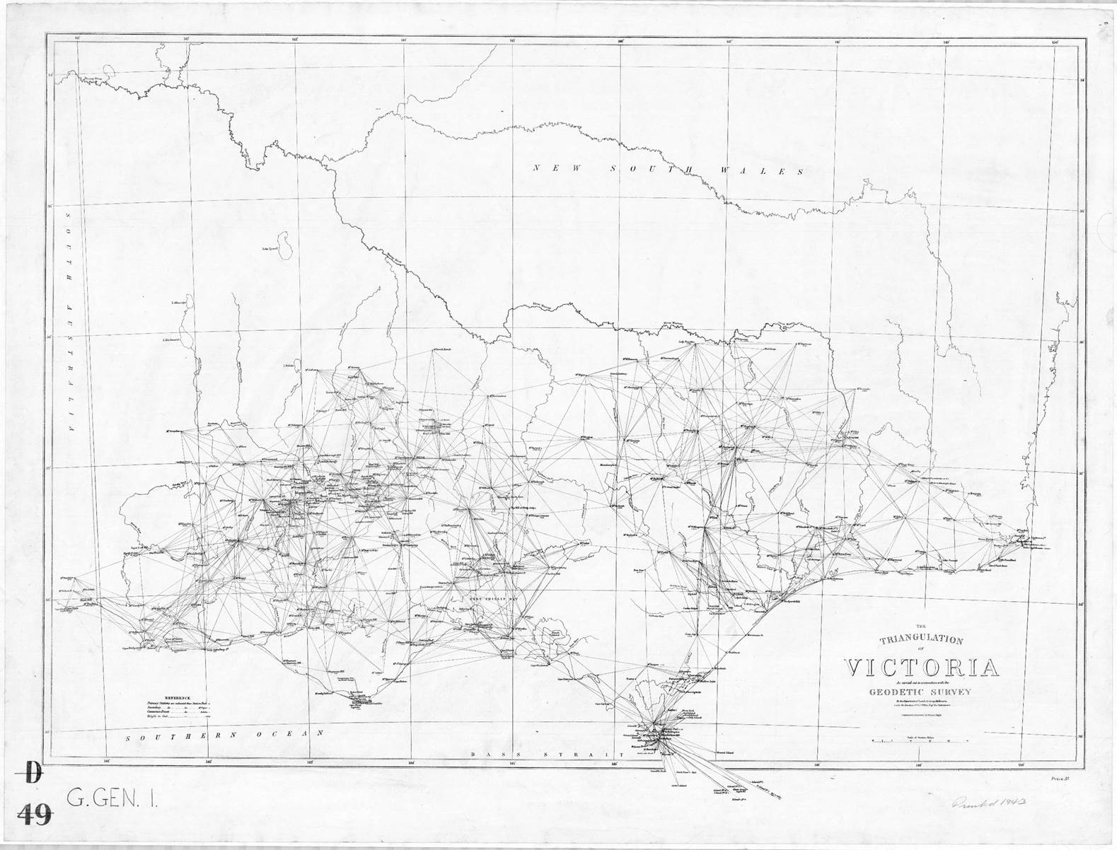
Undated map, produced under the direction of Ellery, showing the extent of the triangulation undertaken as part of the Geodetic Survey of Victoria.